Lab de test
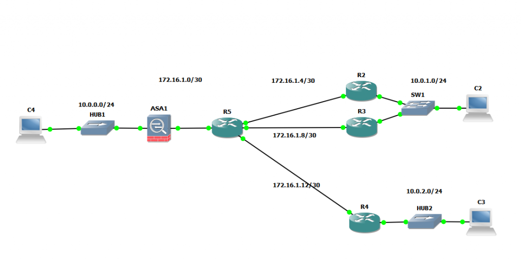
Mise en place d’un Tunnel VPN entre ASA1 et R2
Configuration du Cisco ASA
La partie basique (adresse IP, route):
ASA Version 8.4(2)
!
hostname ciscoasa
!
interface GigabitEthernet0
 nameif OUTSIDE
 security-level 0
 ip address 172.16.1.2 255.255.255.252
!
interface GigabitEthernet1
 nameif INSIDE
 security-level 100
 ip address 10.0.0.254 255.255.255.0
!
route OUTSIDE 0.0.0.0 0.0.0.0 172.16.1.1 1
La configuration des ACL pour valider le routage:
access-list OUTSIDE extended permit icmp any any
access-list INSIDE extended permit icmp any any
access-group OUTSIDE in interface OUTSIDE
access-group INSIDE in interface INSIDE
Configuration du tunnel Lan2Lan vers R2 (172.16.1.5) :
Négociation phase 1 :
crypto ikev1 enable OUTSIDE
crypto ikev1 policy 1
 authentication pre-share
 encryption 3des
 hash sha
 group 2
 lifetime 43200
crypto ikev1 policy 65535
 authentication pre-share
 encryption 3des
 hash sha
 group 2
 lifetime 86400
La transform-set :
crypto ipsec ikev1 transform-set FirstSet esp-3des esp-sha-hmac
La crypto map pour permettre la discution entre les deux Lan distants 10.0.0.0/24 et 10.0.1.0/24:
crypto map Site1 1 match address l2l_list
crypto map Site1 1 set peer 172.16.1.5
crypto map Site1 1 set ikev1 transform-set FirstSet
Avec l’ACL qui va bien “l2l_list”:
access-list l2l_list extended permit ip 10.0.0.0 255.255.255.0 10.0.1.0 255.255.255.0
Le tunnel :
tunnel-group 172.16.1.5 type ipsec-l2l
tunnel-group 172.16.1.5 ipsec-attributes
Configuration du router
La partie crypto :
crypto isakmp policy 1
 encr 3des
 authentication pre-share
 group 2
 lifetime 43200
crypto isakmp key mypresharekey address 172.16.1.2
!
!
crypto ipsec transform-set FirstSet esp-3des esp-sha-hmac
 mode transport
!
crypto map Site1 1 ipsec-isakmp
 set peer 172.16.1.2
 set transform-set FirstSet
 match address l2l_list
L’ACL :
ip access-list extended l2l_list
 permit ip 10.0.1.0 0.0.0.255 10.0.0.0 0.0.0.255
Appliquer la crypto-map sur l’interface :
interface FastEthernet0/0
 ip address 172.16.1.5 255.255.255.252
 duplex auto
 speed auto
 crypto map Site1
Test entre C2 et C4 :
On detruit le tunnel avant pour vérifier la négo :
R2#clear crypto sa peer 172.16.1.2
R2#
*Mar 1 07:13:16.878: IPSEC(delete_sa): deleting SA,
 (sa) sa_dest= 172.16.1.5, sa_prot= 50,
 sa_spi= 0x660495CC(1711576524),
 sa_trans= esp-3des esp-sha-hmac , sa_conn_id= 2000
*Mar 1 07:13:16.882: IPSEC(delete_sa): deleting SA,
 (sa) sa_dest= 172.16.1.2, sa_prot= 50,
 sa_spi= 0x3229E45(52600389),
 sa_trans= esp-3des esp-sha-hmac , sa_conn_id= 2001
*Mar 1 07:13:16.886: IPSEC(delete_sa): deleting SA,
 (sa) sa_dest= 172.16.1.5, sa_prot= 50,
 sa_spi= 0x8C10C1FD(2349908477),
 sa_trans= esp-3des esp-sha-hmac , sa_conn_id= 2002
*Mar 1 07:13:16.886: IPSEC(delete_sa): deleting SA
R2#,
 (sa) sa_dest= 172.16.1.2, sa_prot= 50,
 sa_spi= 0x9ED911A8(2665025960),
 sa_trans= esp-3des esp-sha-hmac , sa_conn_id= 2003
Le tunnel n’est pas négocier :
R2#sh crypto isakmp sa
dst src state conn-id slot
On lance un ping pour monter le tunnel:
VPCS[8]> ping 10.0.0.1
10.0.0.1 icmp_seq=1 timeout
10.0.0.1 icmp_seq=2 ttl=63 time=127.000 ms
10.0.0.1 icmp_seq=3 ttl=63 time=56.000 ms
10.0.0.1 icmp_seq=4 ttl=63 time=81.000 ms
10.0.0.1 icmp_seq=5 ttl=63 time=59.000 ms
La négociation se fait :
R2#
*Mar 1 07:16:25.826: IPSEC(sa_request): ,
 (key eng. msg.) OUTBOUND local= 172.16.1.5, remote= 172.16.1.2,
 local_proxy= 10.0.1.0/255.255.255.0/0/0 (type=4),
 remote_proxy= 10.0.0.0/255.255.255.0/0/0 (type=4),
 protocol= ESP, transform= esp-3des esp-sha-hmac ,
 lifedur= 3600s and 4608000kb,
 spi= 0xF0D3BA7D(4040407677), conn_id= 0, keysize= 0, flags= 0x400E
*Mar 1 07:16:26.270: IPSEC(validate_proposal_request): proposal part #1,
 (key eng. msg.) INBOUND local= 172.16.1.5, remote= 172.16.1.2,
 local_proxy= 10.0.1.0/255.255.255.0/0/0 (type=4),
 remote_proxy= 10.0.0.0/255.255.255.0/0/0 (type=4),
 protocol= ESP, transform= esp-3des esp-sha-hmac ,
 lifedur= 0s and 0kb,
 spi= 0x0(0), conn_id= 0, keysize= 0, flags= 0x2
*Mar 1 07:16:26.274: IPSEC(kei_proxy): head = Site1, map->ivrf = , kei->ivrf =
*Mar 1 07:16:26.290: IPSEC(key_engine): got a queue event...
*Mar 1 07:16:26.290: IPSEC(initialize_sas): ,
 (key eng. msg.) INBOUND local= 172.16.1.5, remote= 172.16.1.2,
 local_proxy= 10.0.1.0/255.255.255.0/0/0 (type=4),
 remote_proxy= 10.0.0.0/255.255.255.0/0/0 (type=4),
 protocol= ESP, transform= esp-3des esp-sha-hmac ,
 lifedur= 3600s and 4608000kb,
 spi= 0xF0D3BA7D(4040407677), conn_id= 2000, keysize= 0, flags= 0x2
*Mar 1 07:16:26.290: IPSEC(initialize_sas): ,
 (key eng. msg.) OUTBOUND local= 172.16.1.5, remote= 172.16.1.2,
 local_proxy= 10.0.1.0/255.255.255.0/0/0 (type=4),
 remote_proxy= 10.0.0.0/255.255.255.0/0/0 (type=4),
 protocol= ESP, transform= esp-3des esp-sha-hmac ,
 lifedur= 3600s and 4608000kb,
 spi= 0xD6AA4151(3601482065), conn_id= 2001, keysize= 0, flags= 0xA
*Mar 1 07:16:26.294: IPSEC(kei_proxy): head = Site1, map->ivrf = , kei->ivrf =
*Mar 1 07:16:26.298: IPSEC(add mtree): src 10.0.1.0, dest 10.0.0.0, dest_port 0
*Mar 1 07:16:26.298: IPSEC(create_sa): sa created,
 (sa) sa_dest= 172.16.1.5, sa_prot= 50,
 sa_spi= 0xF0D3BA7D(4040407677),
 sa_trans= esp-3des esp-sha-hmac , sa_conn_id= 2000
*Mar 1 07:16:26.298: IPSEC(create_sa): sa created,
 (sa) sa_dest= 172.16.1.2, sa_prot= 50,
 sa_spi= 0xD6AA4151(3601482065),
 sa_trans= esp-3des esp-sha-hmac , sa_conn_id= 2001
Le tunnel est donc maintenant négocié:
R2#sh crypto isakmp sa detail
Codes: C - IKE configuration mode, D - Dead Peer Detection
 K - Keepalives, N - NAT-traversal
 X - IKE Extended Authentication
 psk - Preshared key, rsig - RSA signature
 renc - RSA encryption
C-id Local Remote I-VRF Encr Hash Auth DH Lifetime Cap.
1 172.16.1.5 172.16.1.2 3des sha psk 2 11:57:55
R2#sh crypto isakmp sa
dst src state conn-id slot
172.16.1.2 172.16.1.5 QM_IDLE 1 0
Vu du debug sur le asa :
ciscoasa# ICMP echo request from OUTSIDE:10.0.1.1 to INSIDE:10.0.0.1 ID=28916 seq=1 len=64
ICMP echo reply from INSIDE:10.0.0.1 to OUTSIDE:10.0.1.1 ID=28916 seq=1 len=64
ICMP echo request from OUTSIDE:10.0.1.1 to INSIDE:10.0.0.1 ID=29172 seq=2 len=64
ICMP echo reply from INSIDE:10.0.0.1 to OUTSIDE:10.0.1.1 ID=29172 seq=2 len=64
ICMP echo request from OUTSIDE:10.0.1.1 to INSIDE:10.0.0.1 ID=29428 seq=3 len=64
ICMP echo reply from INSIDE:10.0.0.1 to OUTSIDE:10.0.1.1 ID=29428 seq=3 len=64
ICMP echo request from OUTSIDE:10.0.1.1 to INSIDE:10.0.0.1 ID=29684 seq=4 len=64
ICMP echo reply from INSIDE:10.0.0.1 to OUTSIDE:10.0.1.1 ID=29684 seq=4 len=64
ICMP echo request from OUTSIDE:10.0.1.1 to INSIDE:10.0.0.1 ID=29940 seq=5 len=64
ICMP echo reply from INSIDE:10.0.0.1 to OUTSIDE:10.0.1.1 ID=29940 seq=5 len=64
ciscoasa# show crypto ipsec sa peer 172.16.1.5
peer address: 172.16.1.5
 Crypto map tag: Site1, seq num: 1, local addr: 172.16.1.2
access-list l2l_list extended permit ip 10.0.0.0 255.255.255.0 10.0.1.0 255.255.255.0
 local ident (addr/mask/prot/port): (10.0.0.0/255.255.255.0/0/0)
 remote ident (addr/mask/prot/port): (10.0.1.0/255.255.255.0/0/0)
 current_peer: 172.16.1.5
#pkts encaps: 14, #pkts encrypt: 14, #pkts digest: 14
 #pkts decaps: 14, #pkts decrypt: 14, #pkts verify: 14
 #pkts compressed: 0, #pkts decompressed: 0
 #pkts not compressed: 14, #pkts comp failed: 0, #pkts decomp failed: 0
 #pre-frag successes: 0, #pre-frag failures: 0, #fragments created: 0
 #PMTUs sent: 0, #PMTUs rcvd: 0, #decapsulated frgs needing reassembly: 0
 #send errors: 0, #recv errors: 0
local crypto endpt.: 172.16.1.2/0, remote crypto endpt.: 172.16.1.5/0
 path mtu 1500, ipsec overhead 58, media mtu 1500
 current outbound spi: F0D3BA7D
 current inbound spi : D6AA4151
inbound esp sas:
 spi: 0xD6AA4151 (3601482065)
 transform: esp-3des esp-sha-hmac no compression
 in use settings ={L2L, Tunnel, }
 slot: 0, conn_id: 167936, crypto-map: Site1
 sa timing: remaining key lifetime (kB/sec): (4373998/3328)
 IV size: 8 bytes
 replay detection support: Y
 Anti replay bitmap:
 0x00000000 0x00007FFF
 outbound esp sas:
 spi: 0xF0D3BA7D (4040407677)
 transform: esp-3des esp-sha-hmac no compression
 in use settings ={L2L, Tunnel, }
 slot: 0, conn_id: 167936, crypto-map: Site1
 sa timing: remaining key lifetime (kB/sec): (4373998/3328)
 IV size: 8 bytes
 replay detection support: Y
 Anti replay bitmap:
 0x00000000 0x00000001
Mise en place d’un second tunnel vers R4
La configuration de R4 est identique à R2 sauf pour l’ACL qui change de réseau interne : 10.0.2.0/24
ip access-list extended l2l_list
 permit ip 10.0.2.0 0.0.0.255 10.0.0.0 0.0.0.255
Pour le ASA on ajoute un peer à la crypto map existante :
crypto map Site1 2 match address split-tunnel_site2
crypto map Site1 2 set peer 172.16.1.13
crypto map Site1 2 set ikev1 transform-set FirstSet
tunnel-group 172.16.1.13 type ipsec-l2l
tunnel-group 172.16.1.13 ipsec-attributes
 ikev1 pre-shared-key *****
avec l’ACL pour le nouveau réseau :
access-list split-tunnel_site2 extended permit ip 10.0.0.0 255.255.255.0 10.0.2.0 255.255.255.0
Et voila le second tunnel est prêt !! Nous avons maintenant deux tunnels par exemple les branch office du HQ ou l’on a le HUB ASA.
L’idée maintenant serait de pouvoir faire communiquer les deux SPOKE entre eux via le HUB.
SPOKE to SPOKE
Pour cette partie nous allons devoir mettre a jour les ACL de chaque crypto-map pour que le trafic puisse passer via les tunnels.
R2#sh access-lists
Extended IP access list l2l_list
 10 permit ip 10.0.1.0 0.0.0.255 10.0.0.0 0.0.0.255 (520 matches)
 20 permit ip 10.0.1.0 0.0.0.255 10.0.2.0 0.0.0.255 (534 matches)
R4#sh access-lists
Extended IP access list l2l_list
 10 permit ip 10.0.2.0 0.0.0.255 10.0.0.0 0.0.0.255 (27 matches)
 20 permit ip 10.0.2.0 0.0.0.255 10.0.1.0 0.0.0.255 (56 matches)
Et la partie ASA:
access-list l2l_list extended permit ip 10.0.0.0 255.255.255.0 10.0.1.0 255.255.255.0
access-list l2l_list extended permit ip 10.0.2.0 255.255.255.0 10.0.1.0 255.255.255.0
access-list split-tunnel_site2 extended permit ip 10.0.0.0 255.255.255.0 10.0.2.0 255.255.255.0
access-list split-tunnel_site2 extended permit ip 10.0.1.0 255.255.255.0 10.0.2.0 255.255.255.0
Attention ce n’est pas terminé, il faut également permettre la discussion inter interface sur le ASA pour le trafic passe.
ciscoasa# sh run | i same
same-security-traffic permit intra-interface
Il faudra renégocier également les tunnels pour que le trafic passe et les crypto-map se mettent a jour.
Voila nous avons maintenant une archi HUB and SPOKE qui fonctionne.
VPCS[8]> trace 10.0.2.1
trace to 10.0.2.1, 8 hops max, press Ctrl+C to stop
 1 10.0.1.252 27.000 ms 5.000 ms 10.000 ms
 2 * * *
 3 *10.0.2.1 71.000 ms (ICMP type:3, code:3, Destination port unreachable)
Afficher les tunnels sur le ASA :
ciscoasa# sh vpn-sessiondb
---------------------------------------------------------------------------
VPN Session Summary
---------------------------------------------------------------------------
 Active : Cumulative : Peak Concur : Inactive
 ----------------------------------------------
Site-to-Site VPN : 2 : 42 : 2
 IKEv1 IPsec : 2 : 42 : 2
---------------------------------------------------------------------------
Total Active and Inactive : 2 Total Cumulative : 42
Device Total VPN Capacity : 0
Device Load : 0%
***!! WARNING: Platform capacity exceeded !!***
---------------------------------------------------------------------------
---------------------------------------------------------------------------
Tunnels Summary
---------------------------------------------------------------------------
 Active : Cumulative : Peak Concurrent
 ----------------------------------------------
IKEv1 : 2 : 42 : 2
IPsec : 2 : 22 : 4
---------------------------------------------------------------------------
Totals : 4 : 64
---------------------------------------------------------------------------
ciscoasa# sh vpn-sessiondb l2l
Session Type: LAN-to-LAN
Connection : 172.16.1.5
Index : 41 IP Addr : 172.16.1.5
Protocol : IKEv1 IPsec
Encryption : 3DES Hashing : SHA1
Bytes Tx : 1780 Bytes Rx : 2208
Login Time : 18:02:17 UTC Fri Apr 4 2014
Duration : 0h:37m:09s
Connection : 172.16.1.13
Index : 42 IP Addr : 172.16.1.13
Protocol : IKEv1 IPsec
Encryption : 3DES Hashing : SHA1
Bytes Tx : 828 Bytes Rx : 492
Login Time : 18:32:30 UTC Fri Apr 4 2014
Duration : 0h:06m:56s
High availability
Nous allons maintenant créer un second tunnel entre R3 et ASA1 afin de faire un backup du tunnel.
Pour cela on peut reprendre la meme configuration sur R2 et la mettre sur R3 sans oublier d’activer la crypto sur l’interface de sortie fa0/0.
Pour la partie ASA, il faut mettre a jour la crypto-map et ajouter un tunnel à la configuration :
crypto map Site1 1 match address l2l_list
crypto map Site1 1 set peer 172.16.1.5 172.16.1.9
crypto map Site1 1 set ikev1 transform-set FirstSet
tunnel-group 172.16.1.9 type ipsec-l2l
tunnel-group 172.16.1.9 general-attributes
tunnel-group 172.16.1.9 ipsec-attributes
Voila le second tunnel est configuré. Il faut également penser à configurer HSRP entre les deux routeurs pour la partie inside avec un tracking de l’interface fa0/0 par exemple pour faire basculer en cas de perte du lien.
R2#
interface FastEthernet0/1
 description Inside
 ip address 10.0.1.252 255.255.255.0
 duplex auto
 speed auto
 standby ip 10.0.1.254
 standby timers msec 250 1
 standby priority 110
 standby track FastEthernet0/0 20
R3#
interface FastEthernet0/1
 ip address 10.0.1.253 255.255.255.0
 duplex auto
 speed auto
 standby ip 10.0.1.254
 standby timers msec 250 1
 standby preempt
 standby track FastEthernet0/0 20
Dans la plupart des cas cela est suffisant, toutefois on peut remarque si le lien WAN remonte assez rapidement, le tunnel ne sera pas détruit et donc renégocié.
Pour cela nous pouvons configurer le idle-timeout afin de réduire le délais et renégocier plus rapidement. Sur les routeurs la valeur est en seconde alors que sur le ASA nous sommes en minute.
Sur R2 et R3:
crypto ipsec security-association idle-time 60
Sur le ASA :
group-policy grp_policy internal
group-policy grp_policy attributes
 vpn-idle-timeout 1
et appliquer le groupe sur le ou les tunnels :
tunnel-group 172.16.1.13 type ipsec-l2l
tunnel-group 172.16.1.13 ipsec-attributes
tunnel-group 172.16.1.5 type ipsec-l2l
tunnel-group 172.16.1.5 general-attributes
tunnel-group 172.16.1.5 ipsec-attributes
tunnel-group 172.16.1.9 type ipsec-l2l
tunnel-group 172.16.1.9 general-attributes
tunnel-group 172.16.1.9 ipsec-attributes
Voila un debug d’un routeur qui montre la négociation du idle-timeout:
IPSEC(create_sa): starting idle timer, 60 seconds